All-in-One Power Quality Analyzer & PMU
SATEC PM180


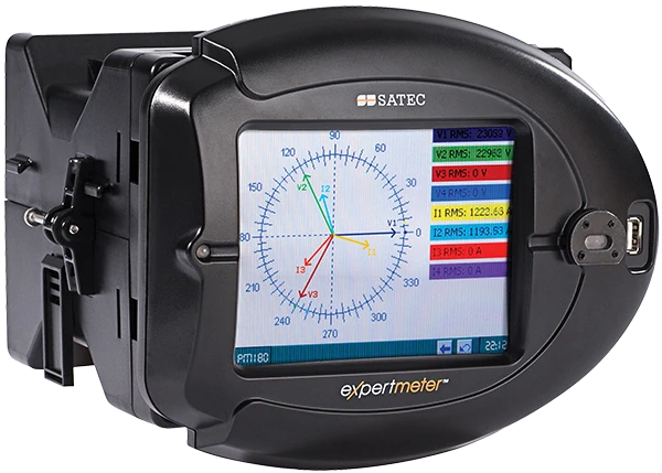
The PM180, our flagship power quality analyzer, seamlessly integrates multiple advanced functionalities into a single device, making it a cost-effective solution.
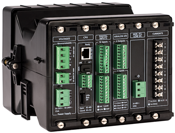
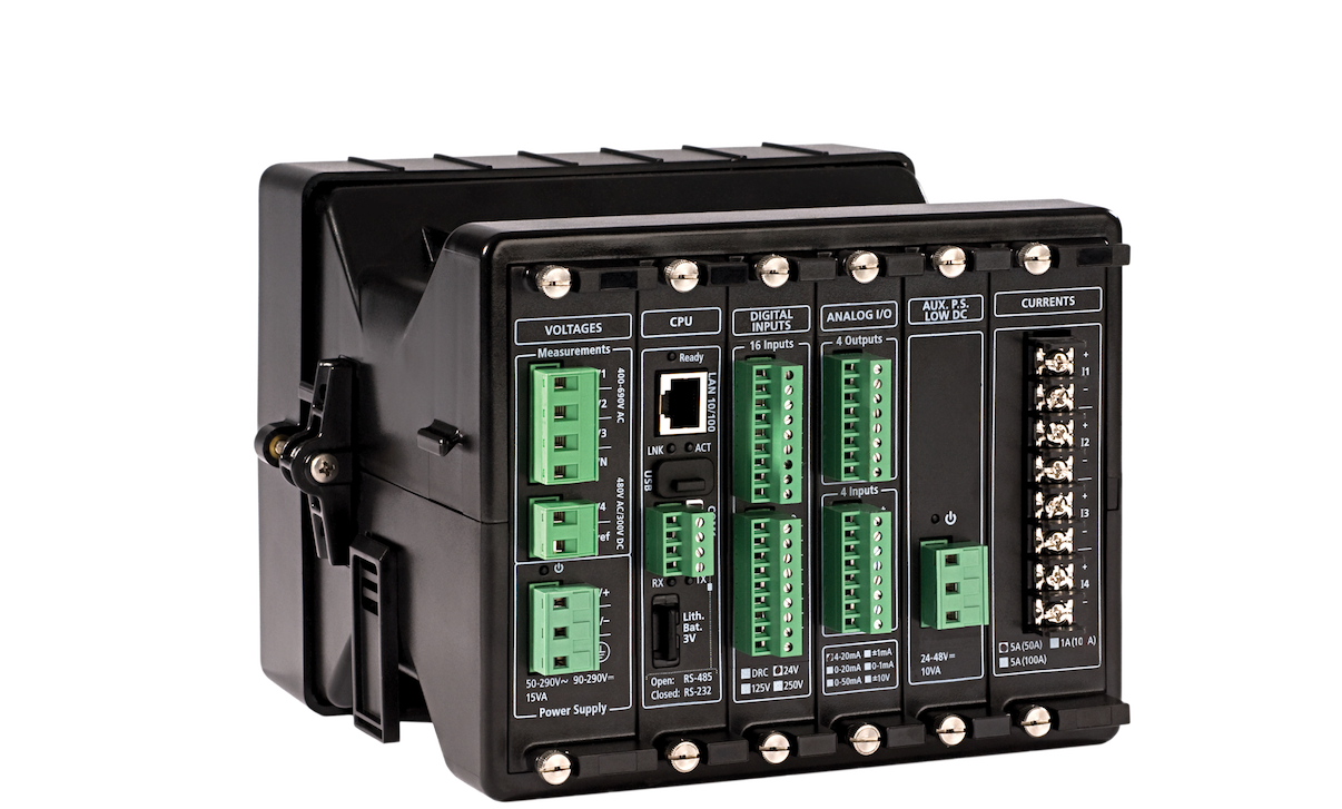
Its unique modular design allows for hot-swapping of various add-on cards, enabling versatile functionality. As a result, it can consolidate and replace several devices, leading to cost savings and space optimization while minimizing complexity.
Power Quality Analyzer
- Certified by NMI as Class A (Edition 3) per IEC 61000-4-30, the PM180 is one of the most advanced analyzers on the market
-
Compliance with ENA EREC G99
Communication
- Protocols: IEC 61850, IEC 60870-5-101/104, DNP3, Modbus
- Interfaces: RS485, Ethernet, IRIG-B
- Optional ports: 2nd ETH, Fiber Optic ETH (TXFX)
Fast Transient Sampling
- Records voltage transients of up to 2kV (L-G) at 1024 samples/cycle per channel
Fault Recorder Module
- Additional current input offers separated metering & protection CT connection, records current faults of up to 200A (40*In)
- Programmable fault threshold and hysteresis
- Current and voltage unbalance
Bay Controller Unit (BCU)
- Monitoring and control capabilities for 2 circuit breakers and 14 circuit switches
Module Configuration
- 3 slots for hot swap plug-in I/O modules
- Up to 3 modules of 16-channel DI
- Up to 3 modules of 8-channel RO
- Up to 2 modules of 4-channel AI/AO
- Accurate time synchronization (SNTP, DI, IRIG-B)
- Redundant Ethernet port, Optically isolated IRIG-B port
Versatile micro-sec resolution time sync
- PTP and IRIG-B


Description
The SATEC PM180 is a high-performance analyzer with versatile applications. Its exceptional performance, combined with the flexible design of expansion cards and installation options (including DIN rail, 4” round, or 92x92mm cutout), allows it to replace multiple devices, resulting in cost savings, space efficiency, and reduced complexity.
High Performance Power Quality Analyzer (PQA) & Recorder
The PM180 is the most advanced power quality analyzer and recorder on the market. It is designed to fully comply with the most demanding industry standard, IEC 61000-4-30 Class A (Edition 3).
It provides power quality reports and statistics according to EN50160, complimented by comprehensive power quality event/data log with waveforms available for detailed Power Quality event analysis. Redundant power supply allows full readiness for any power quality event, including major dips and interruptions.
The individual harmonics and inter-harmonics are analyzed according to IEC 61000-4-7. The instrument also supports directional power harmonics analysis. Flicker is measured and analyzed according to IEC 61000-4-15.
Industrial & Substation Automation Controller with IEC 61850 Protocol
SATEC PM180 is a cost effective solution for electrical substation automation. It can be used either as a bay controller or as a Power Meter with IEC 61850 support.
- PM180 as a Bay Controller Unit (BCU) provides fully automated control of substation switching devices. After the switches are configured in the device, typically no additional logic is required for controller operation, except for interlocking logic. Bay control solutions are customized via control logic and a variety of digital I/O and analog measurements.
- PM180 as Power Meter provides ALL the information required for substation automation. The PM180 extends the life expectancy of electromechanical relays by providing information lacking in electromechanical devices without interfering in the protection scheme.
Sequence of Events (SoE)
SATEC PM180 Sequence of Events (SoE) Recorder designed for an electrical utility substation or industrial environment to record contact openings and closings of field devices, such as electromechanical and microprocessor controlled relays. It includes up to three 16 digital input modules, with up to a total of 48 digital inputs (wet or dry type) with a 1 mSec time resolution between events.
The Sequence of Events (SoE) recorder can log four types of events: digital input events, relay output events, fault events and setpoint events.
Digital Fault Recording (DFR)
SATEC PM180 includes true Digital Fault Recording and Disturbance Recording. The standard device includes four current channels for up to 20xIn (100A @ In=5A) of fault currents. Adding the DFR module allows for separated connection of measurement CTs and protection CTs of up to 40xIn (200A).
Three AC voltage channels and one AC/DC measurement input channels are also included. Multiple PM180 devices can cross trigger for up to 20 cycles of pre-fault information for distributed recording.
Fault information can be exported to PQDIF/COMTRADE format via PAS software. The fault recorder provides 4 measured and recorded currents (including measured neutral current). The event log is complemented by waveform recording.
Revenue Grade Check Meter
Designed for Revenue Grade metering, the PM180 provides a high accuracy energy measurement that can be used to check the utility meter, as well as adding power quality and control functions. For high performance revenue metering, the PM180 includes:
- Exceeding Revenue 0.2S Class Accuracy (IEC 62053-22)
- Built-in Time Of Use (TOU) with a 10 year calendar, 16 types of days and up to 8 tariff changes per day for each daily profile
The precise measurement class of accuracy ensures that the energy readings are better than the utility meter's readings, which makes it trusty when there is a discrepancy between the utility and the PM180 reading.
Phasor Measurement Unit (PMU)
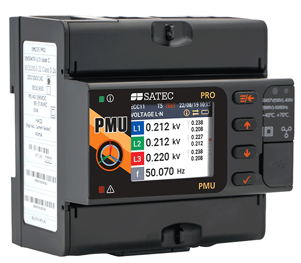
The PM180 Phasor Measurement Unit (PMU) module provides synchrophasor and frequency measurements compliant with the IEEE C37.118.1 P performance class, as well as real-time cyclic exchange of synchronized phasor data with the substation phasor data concentrator (PDC) based on the IEC 61850-9-2 Sampled Value (SV) service.
Motors and Large Load Monitoring
Electrical motors and other large loads are an important part of the electrical equipment and are dominant in the overall consumption. As a result, they significantly affect the energy efficiency and site reliability. Monitoring main motors includes observing their energy consumption, tracking their health and examining their efficiency.
Plug-In Modules

Automation & Control Modules

Digital Inputs
- 16 inputs (total up to 48 DI)
- Optically isolated dry/wet contact
- 24/125/250V DC
- Scan time:
- 1ms @ 60Hz
- 1.25ms @ 50Hz

Relay Outputs
- 8 relays (Total up to 24 RO)
- 8 relays rated at:
- 8A/250V AC
- 5A/24V DC
- 0.25A/250V DC

Analog Inputs/Outputs
- 4AI and 4AO (Total up to 12AI / 12AO)
- Accuracy Class 0.2S FS
- Scan/update time: 2 cycles
- Ranges:
- ±1mA (with 100% overload)
- 0-1mA (with 100% overload)
- 0-20mA
- 4-20mA
Communication Ports

IRIG-B module
- Optically isolated IRIG-B port
- Second RS-422/485 COM port

TX-FX module
- Redundant Ethernet port
- 10/100 Mbit with RJ45 connector
- 100Base FX with SC connector
Measurement / Fault Channels

Transient Recorder Module
- Records voltage transients of up to 2kV (L-G) at 1024 samples/cycle per channel

Fault Recorder Module
- Additional current input offers separated metering & protection CT connection, records current faults of up to 200A (40*In)

PMU Functionality
- Phasor measurement unit (PMU) provides synchrophasor and frequency measurements compliant with the IEEE C37.118.1 P performance class, and real-time cyclic exchange of synchronized phasor data with the substation phasor data concentrator (PDC) based on the IEC 61850-9-2 sampled value (SV) service.
- Full interoperability, featuring:
- IEEE C37.118.2 protocol
- IEC 61850-9-2 protocol
- 5 streaming slots (UDP and TCP protocol)
Redundant Power Supply Module

Auxiliary Power Supply
- 50-290V AC and 40-290V DC, 20W
- 9.6-35 V DC, 20W
(maximum one auxiliary power supply per PM180)
Tech Specs
-
-
Multifunctional Power & Energy Meter
- Accuracy for energy metering
- Class 0.2S per IEC 62053-22
- Class 0.2 per IEC 61557-12
- Real-time cycle-by-cycle measurement of True RMS volts, amps, power, power factor, neutral current, angles, demand, energy and unbalance for voltage and current, frequency, symmetrical components and many more
- Event and parameter data-logging
- Advanced Time of Use (TOU) feature:
- 16 Energy sources, including external digital pulses
- up to 4 seasons
- 4 daily profiles and 8 Tariffs changes per day
- flexible automatic 10-year calendar
- suitable for complex billing schemes
- Sampling frequency: up to 1024* samples per cycle
- KYZ or KY output
- LED indicator for calibration and testing (via optional display)
- Vector diagram and symmetrical components
- IRIG-B / SNTP / DI time synchronization
- 256 MB memory for data-logging
- 4 decimal resolution for frequency readings
- Accuracy for energy metering
-
IEC 61850
- IEC 61850 implemented per Edition 2
- Remote switch control and monitoring via IEC 61850 protocol
- Inter-device GOOSE communications for remote interlocking
- GOOSE Publisher Setup, GOOSE Subscriber Setup and Report Dead-bands
- Configuration of IEC 61850: IED properties, datasets and reports
-
-
Power Quality
- NMI certified for Class A, Edition 3, per IEC 61000-4-30
- EN50160 monitoring, statistics & reports
- Event statistics complimented by waveform recording in 8 channels (4 voltage inputs, 4 current inputs) @ 256/1024 samples/cycle
- V-I angle, THD, TDD and K factor for Voltage and Current and up to the 63rd order harmonic. individual harmonics for V, I, P, Q
- Disturbance Direction Detection: indicating upstream or downstream direction of sags and swells
- Flicker according to IEC 61000-4-15
- Detecting transients as short as 17μs
- Sags/Swells (dips / overvoltage), interruptions, frequency variations, voltage variations
- Voltage unbalance
- Voltage and current individual harmonics (according to IEC 61000-4-7), interharmonics and directional power harmonics (load/source) up to the 63rd harmonic
- Voltage and current THD coefficients
- Symmetrical components
- Programmable thresholds and hysteresis
- Redundant auxiliary power supply for recording major dips and interruptions
- Waveform, power factor & phasor data recorder
- Power quality event recorder
- Event recorder for logging internal diagnostic events, control events and I/O operations
- Selectable sampling rate up to 256 / 1024 (fast transients >78/65μs @ 50/60Hz )
-
Data Logging, Waveform Recording & PLC Programming
- Programmable controller: up to 64 control setpoints, up to 8 conditions OR, AND, arithmetical functions logic, extensive triggers, programmable thresholds and delays, relay control, event-driven data recording
- Supports IEC 61131 PLC Configuration (LD, FBD)
- 8 fast waveform recorders: simultaneous 8-channel AC, one DC: up to 48 digital inputs in a single plot
- Waveform sampling rate 32, 64, 128 or 256 samples per cycle; up to 20 pre-fault cycles (2 cycles of 1024 samples per cycle or 4 cycles with 512 samples per cycle with Transient Module)
- Up to 3.5 min. of continuous waveform recording
- 1-ms resolution for digital inputs
- Onboard memory: 256 MB
- 16 fast Data Recorders (16 parameters on each data log):
- From ½ cycle RMS to 2 hour RMS envelopes
- Up to 20 pre/post-fault cycles
- Programmable data logs on a periodic basis and on internal or external trigger
- ½-cycle response time
- 32 digital internal counters
- 16 programmable timers (½ cycle to 24 hours)
-
Bay Controller (BCU)
- Monitoring and control capabilities for 2 circuit breakers and 14 circuit switches
- One-pole and three-pole switch position monitoring, using two or six contacts
- One control output for switch closing
- Two synchronous control outputs for switch opening devices with one and two opening coils
- Select-close control output for secure switch closing operations
- Two select-open control outputs for secure switch opening operations
- Configurable command pulse duration
- Option for adaptive pulses controlled via setpoint control logic
- Supervision of command execution & reporting on operation termination
- Interlocking logic
- Secure timed-out interlocking bypass logic
- Indication of non-controllable breaker trips
- Switch position substitution option
- Counting of breaker and switch operations
- Logging close / open operations and switch position changes
- Local switch control via setpoint control logic
- Configuration tools: PLC configurator based on IEC 61131-3 protocol, using Functional Block Diagram (FBD) or Ladder Diagram (LD)
-
Digital Fault Recorder (DFR)
- Programmable fault threshold and hysteresis
- Direct reading of fault currents of up to 200 Amps (40 x In, from CT secondary)
- Dual current inputs: from measurement CT and protection CT connection (optional)
- Zero-sequence currents and voltages
- Current and voltage unbalance Under-voltage, neutral current
- Ready-for-use fault reports—fault currents magnitude and duration, coincident volts magnitude, fault waveforms and RMS trace
- Selectable pre-fault / post-fault recording length
- Programmable post fault on any internal and/or external trigger condition
- Disturbance capture recording
- Distance to fault calculation
- Waveforms from multiple locations
- View faults and receive alerts via SATEC Expertpower™ software platform
-
Distance to Fault Calculation
- Compensation for CT / PT errors, resulting in average accuracy of 0.5% (depending on PT, CT and time synchronization accuracy)
- Supported line configurations
- Single line
- Parallel lines
- Partially parallel lines
- A line with a branch
- Required parameters
- Line/s configuration
- Line/s parameters (impedance, length, etc.)
- Compensation parameters for CT & PT
- Detected Faults
- Three-phase short circuit
- Two-phase short circuit
- Two-phase short circuit to ground
- Single-phase short circuit to ground
- Single-phase open wire
- Fault detection information
- Fault classification (type and phase/s)
- Distance to fault (km or miles)
- Duration of fault
-
Phasor Measurement Unit (PMU)
- IEEE C37.118.1 Compliance
- M-Class
- P-Class
- IEEE C37.118.1 three-phase voltage and current phasor measurements synchronized to a common UTC time reference (e.g. GPS), using an IRIG-B timecode source or an IEEE 1588 PTPv2 master clock source
- IEEE C37.118.1 synchronous frequency and Rate of Change of Frequency (ROCOF) measurements
- Expected total vector error (TVE): less than 0.5%
- Streaming of phasor data over Ethernet using IEC 61850-9-2 multicast sampled value (SV)
- Streaming rate: from 1 to 50 or 60 frames/s @ 50 or 60Hz, respectively
- IEEE C37.118.2 commanded client-server UDP and TCP data transmission and spontaneous UDP data transmission over IP protocol
- Optional IEEE C37.118.2 frame extensions with analog data (total active, reactive and apparent power and power factor) and digital status data (up to 32 inputs)
- Streaming of phasor data over Ethernet using the IEC 61850-9-2 multicast sampled value (SV) service with IEEE C37.118.2 compliant mapping of synchrophasor data upon IEC 61850-9-2 and IEC 61850-90-5 guidelines
- IEEE C37.118.1 Compliance
-
Variable Current Inputs
- 4 dual purpose current inputs (3 phase + Neutral current), calibrated to 1A or 5A nominal:
- Class 0.2S revenue grade accuracy: up to 4 × nominal current (4A and 20A, respectively; designed for measurement CTs’ secondary current)
- Basic Fault current reading: up to 10 × nominal current (10A and 50A, respectively, designed for protection CTs’ secondary current)
- Fault Recorder Modules:
- Extended Fault Current reading: up to 40 × nominal current (200A, designed for protection CTs’ secondary current)
- HACS: special 40mA inputs for SATEC’s High Accuracy Current Sensors
- CS1S: specific inputs for 100A split-core HACS, calibrated to 5A
- CS1H: specific inputs for 100A HACS handheld current clamps, calibrated to 5A
- 3V AC: inputs for generic current clamps (Rogowski)
- 4 dual purpose current inputs (3 phase + Neutral current), calibrated to 1A or 5A nominal:
-
Wide Range Voltage Inputs
- Three galvanically isolated AC voltage inputs
- Impulse dielectric withstand: 6kV
- Nominal voltage: 100-828V AC (L-L)
- Available options:
- 120V AC Nominal voltage
- 690V AC Nominal voltage
- Operating range:
- Wide range application up to 828V AC
- 5th AC/DC voltage input:
- monitoring substation battery (up to 300V DC)
-
Communication Interfaces
- Built-in:
- RS-485
- USB
- ETH 10/100Base-T
- IRIG-B
- Optional / additional: (1 per device):
- Fiber optic TXFX including 2nd Ethernet port and 2nd RS485 port
- 2G/3G/4G cellular modem including 2nd RS485 port
- Built-in:
-
Communication Protocols
- Modbus
- ASCII
- DNP 3.0
- IEC 60870-5-101/104
- IEC 61850
-
Display Options
- Transducer version: no display. Installed on DIN-rail
- Graphic color display: supplied with a 5.7″ touchscreen
- LED Display: 3 line ultra bright LED display
-
Real-Time Clock & Synchronization
- Real-Time Clock with maximum 5 seconds drift per month @ 25°C
- Provides 1 msec time resolution via IRIG-B time code input or satellite clock for common time base (requires IRIG-B module)
- Periodic clock synchronization from an SNTP server, as SNTP client
- Time sync from digital input with 1ms accuracy
-
Power Supply
- Built-in: 85-265V AC / 88-290V DC
- Additional options:
- AUX 85-265V AC / 88-290V DC
- AUX 9.6-35V DC
-
Digital I/O
- 16 Digital Inputs
- Dry contact sensing: 24V DC Internal power supply
- Wet contact sensing: External power supply 24/48/125/250V DC
- 8 Relay Outputs - Electromechanical (SPST Form A)
- 8A/250V AC
- 5A/30 VDC
- 0.25A/250V DC
- 5A/24V DC
- Combo: 8 Digital Inputs + 4 Relay Outputs
- 8DI/4RO EMR DRC
- 8DI/4RO SSR DRC
- 8DI/4RO EMR 24V
- 8DI/4RO SSR 24V
- 8DI/4RO EMR 125V
- 8DI/4RO SSR 125V
- 8DI/4RO EMR 250V
- 8DI/4RO SSR 250V
- 16 Digital Inputs
-
-
Analog I/O
- Combo: 4 analog inputs + 4 analog outputs. Available options (ratings are identical for inputs and outputs):
- ±1 mA, max. load 10 kΩ (100% overload)
- 0-20 mA, max. load 510Ω
- 4-20 mA, max. load 510Ω
- 0-1 mA, max. load 10 kΩ (100% overload)
- Combo: 4 analog inputs + 4 analog outputs. Available options (ratings are identical for inputs and outputs):
-
Enhanced Meter Security
- 3 levels Password security for protecting meter setups and accumulated data from unauthorized changes
- Defining up to 20 users in different access levels
- Extra-complex password is required
- Access and configuration log is automatically and continuously recorded, documenting all user activity
-
Mounting
- Panel mount
- DIN Rail mount
- 19″ rack installation
- Complies with EN50022
-
Downloads
Marketing Materials
Technical Information
- PM180 Installation Manual
- PM180 Operation Manual
- EDL180 Portable Event & Data Logger - Installation & Operation Manual
- RGM180 Remote Display - Quick Start Guide
- PM180 PLC Configurator Guide
- PM180 Modbus Communications Protocol
- PM180 DNP3 Communications Protocol
- PM180 IEC 61850 Communications Protocol
- PM180 IEC60870-5-101/104 Communications Protocol
- PM180 IEEE C37.118.2 Synchrophasor Data Transfer Protocol
Application Notes
- PM180 Phasor Measurement Unit (PMU) - Application Note
- PM180 Bay Controller Unit (BCU) - Application Note
- PM180 EN 50160:2010 Power Quality Recorder (PQR) - Application Note
- PM180 Fault Locator - Application Note
- PM180 Disturbance Direction Detection - Application Note
- PM180 Enhanced Security - Application Note


